Bent bamboo · kit design log
One socket, four angles, and rods that push back.
A printed PLA joint system for quarter inch bamboo, the 610 mm sticks sold everywhere, which calipered at 5.8 to 6.2 mm rather than the 6.35 the label implies. Every socket is the same socket, so any joint mates with any joint, and the whole system is designed around bending the rod rather than keeping it straight. This page is the design log, not a shop.
One part printed, nothing assembled, as of 2026-08-04. This block first said "Nothing has been printed, no fit coupon has run on these parts", and that stopped being true the same night it was written: the 4 degree bend guide printed on 2026-08-02 at 23:46, after the first guide design failed its own numbers. Its designed bend was smaller than the slop in its own bore, and real rods gauge 5.8 to 6.2 mm against the assumed 6.35. The correction section below carries the full account. The joints themselves are unprinted, their bores unproven at this depth on this machine, and nothing has been assembled.
The bore constants carry over from this project's earlier printed bamboo work, the stave shelf gauge and the stand. Every fit is machine and depth conditional, so on these sockets they are guesses with good ancestry until a coupon prints. The ledger below keeps that line visible.
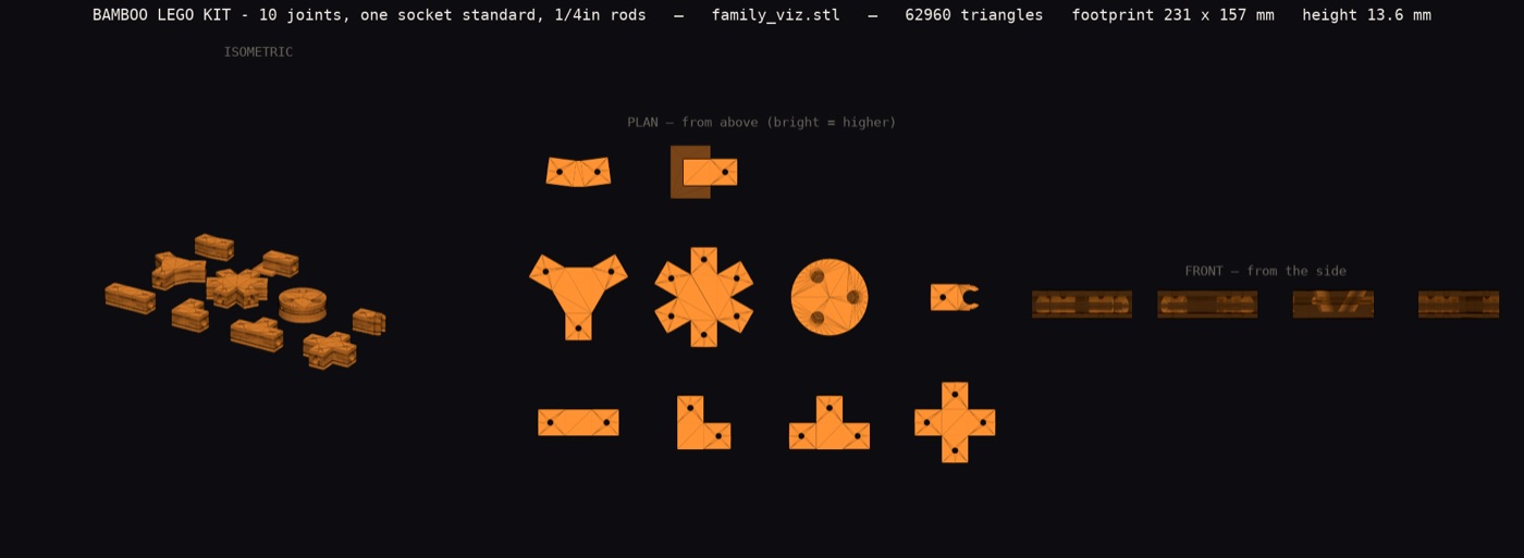
Provenance: recovered 2026-08-04. The image names its own source across the top: family_viz.stl at 62,960 triangles, drawn by tools/render_stand_stl.py in the public crackle repository. That build file has since been rebuilt to 82,502 triangles, so today's copy renders a later kit. Re-rendering the earlier revision (commit 539f55a, 2026-08-02) reproduces this image, checked pixel against pixel on 2026-08-04. Extracted from the page into a file on 2026-08-04.
Physics simulation
Not yet for this kit, honestly. The physics engine is live and already judging the marble chute at sim.senku.im, viewer and QA gate running the same code. The bamboo scenario, a joint holding a 610 mm rod under a 20 newton end load, is queued for after the v2 joints land, because simulating parts that are being redesigned this hour would waste the run. When it lands, the viewer and its verbatim QA log appear here.
One socket, everywhere
The LEGO trick was never the brick, it is the stud: one interface repeated without exception, so every part is compatible with every part by construction. Here the interface is a socket, one flat 7.0 mm bore, 24.10 mm deep. The bore is stick size and nothing more, and the gap to a given stick is taken up by a graded TPU shim ring rather than by a fit adder, because the rods measure 5.8 to 6.2 and no single bore can be snug on all of them. The depth is not a choice, it is solved from the load case. Both numbers replace what this page carried until 2026-08-02, a 12 mm socket in a 7.05 snug or 7.65 slide bore, and the correction below has the account.
Through every socket runs a 3 mm cross hole. It is a drill guide first: seat the rod, run a 3 mm bit through the hole and through the captive rod, then push a standard bamboo skewer through boss, rod and boss. The skewer is a shear pin: the rod cannot pull out or spin, no glue anywhere, and the pin is the same material as the frame. The workflow this enables is the point: friction fit while you experiment, take it apart freely, then pin only the joints you decide to keep. A structure graduates one skewer at a time and stays disassemblable by pulling pins. Bent rods are why it is not optional: a bowed rod pushes outward against its sockets forever, and the pin guarantees that push can never walk the rod out.
Angles are quantized to 45, 60, 90 and 120 degrees. Four angles cover square frames, triangulated frames and hex layouts, and quantization is the compatibility: any part meets any part at an angle both already agree on. The one exception is the 15 degree end joint, and the next section is why it exists.
socket · bore 7.0 flat, 24.10 mm deep, the depth derived from the load case
shim · graded TPU ring on the rod, sized per stick, its squeeze is the grip
pin · 3 mm cross hole through every socket, a bamboo skewer is the pin
angles · 45 / 60 / 90 / 120, plus the 15 degree arc absorber
The bend is the point
Straight-stick construction sets exist everywhere. This one assumes the rod arrives bent. The limit is known from the stave shelf's geometry work: a 6.35 rod snaps below roughly a 318 mm bend radius, a figure computed from literature bamboo properties, not yet measured on these sticks. The kit's standard arcs stay at radius 1000 and up, at least three times outside the snap radius, so a rod on a kit arc is loafing.
A bowed rod does not meet its socket square. On the reference arc, a 32 mm bow over a 521 mm chord for a radius of 1079, the rod arrives about 14 degrees off the socket axis. The 15 degree end joint exists for exactly that: it absorbs the arrival angle by design instead of asking a straight socket to take it as a side load.
The reward for tolerating all this is preload. A bowed rod pushes outward against its sockets for as long as it stays bowed, so a preloaded frame cannot rattle: the slop is spent permanently. That physics is worked through, on paper and in emitted geometry, in the stave shelf design. The built precedent this kit actually leans on is the ball lift, whose frame is quarter inch bamboo held by printed joints and standing. Bowed preload itself has not been assembled by anyone here yet, and the ledger says so.
Kit v1: ten parts, one interface
Every part below is the same socket repeated at quantized angles. No part has a special interface, which is the whole idea.
- inline sleeve · two sockets at 180. Extends a rod or splices a broken one.
- L90 · the square corner.
- T · a 90 degree branch off a running rod.
- X · a full cross, four ways in one plane.
- Y120 · three ways at 120, the hex corner.
- rosette hub · six sockets at 60 in one plane. The wheel centre.
- 3D node · sockets out of the plane, takes a flat frame into the third axis.
- saddle clamp · grips a bowed rod mid arc and adds a branch, no unthreading.
- 15 degree end joint · the arc absorber. A bowed rod lands in it square.
- foot cap · closes a rod end and gives it a floor to stand on.
bend guide · the angle dial: three bores, the middle one offset by the sagitta; thread a rod and it is held in a bow, and because bamboo is elastic the guide stays on as the bow keeper. It serves 2 to 8 degrees between the straight tails. See the correction below before reading any older number.
Every bend, and why the jig is the size it is
There are four bend guides. Pick one and the drawing below shows what it does to a 24 inch rod: where the three stations grip, the shape the rod actually takes between them, and the straight tails it leaves at each end. The curve is the real deflection shape of a beam loaded at three points, not a decorative arc.
Why 8 degrees needs a jig longer than your forearm
Three point bending puts all the curvature in one place. Integrating the moment gives two facts that fight each other, and eliminating the offset between them collapses both to a single line: the angle equals the half span divided by the tightest radius the rod survives. Bamboo of this stock snaps below a radius of about 318 mm, and the jigs are sized to stay three times clear of that, at 954 mm.
So the span is fixed by the angle you want, and nothing about the design can shrink it. Ask for more bend and the jig grows in proportion. Ask for a tighter jig and the rod breaks. The 8 degree guide is 291 mm tall and 123 grams for a tool you use once per rod, and past about 9.5 degrees the bar runs off the print bed entirely.
The fix is not a better jig, it is a different shape of jig. Holding the rod on a constant radius instead of at three points spreads the curvature evenly, and then the length you have to build is the arc rather than twice the half span: 2.2 times shorter for the same bend at the same safe radius. Better still, a second bamboo rod can be the straight spine, so the only printed parts are small clips joining the two at graded offsets. That is roughly 20 grams instead of 123. It is designed but not built.
What every file is
Twenty two printable files have accumulated here and their names are not self explanatory. This is the whole list. Nothing in it has been printed.
| File | What it is | When you want it |
|---|---|---|
| sleeve | Straight socket, rod to rod | Making a long rod out of two short ones |
| l90 | Right angle, two sockets | A corner |
| t | Three sockets in a plane, one at 90 | A branch off a straight run |
| x | Four sockets in a plane, crossing | A grid intersection |
| y120 | Three sockets in a plane at 120 | Hexagon frames, the stiffest flat layout |
| hub6 | Six sockets in a plane | A wheel or a full hex node |
| tetra | Sockets out of the plane | Going three dimensional |
| saddle | Clamps mid rod and adds a branch | Branching off a bowed rod without unthreading it |
| angle15 | End joint at 15 degrees | Receiving a bowed rod square, so the bow does not fight the socket |
| foot | Closes a rod end, gives it a floor | Anywhere a rod touches the ground |
| bend_guide_a2 / a4 / a6 / a8 | The four bending jigs, one per angle | Putting a known bow into a rod. See the demo above |
| shim_5.8 to shim_6.2 | Five graded flexible rings, one per 0.1 mm of rod | Every joint. The rods vary and the bores do not |
| shim_gauge | Comb that sorts rods into the five grades | First, before any shim is useful |
| family_viz / shim_family_viz | Not parts. All the joints, or all the shims, laid out together to look at | Never print these |
The last row is the honest answer to why the folder looks confusing: two of the files are pictures rather than parts, and they are among the largest.
Correction, 2026-08-02: this page claimed 15 to 35 degrees
It said the bend guide delivered 15 to 35 degrees over a 24 inch stick. That was wrong, and the correction stays here rather than being quietly edited away. Oleg looked at the part and said it did not appear to have any holes. It did have one, a 7.65 mm bore running its whole length, and going to look for it turned up three real faults.
The bend it imposed was smaller than the slop in its own bore. The rods measure 5.8 to 6.2 mm in a 7.65 mm slide bore, so the rod can wander 1.85 mm, against a designed offset of 0.91 mm at the 15 degree setting and 1.81 mm at 30. The rod could sit dead straight inside the jig and nothing stopped it.
The angle label was 6.3 times optimistic. The old maths fitted a circle through the three bores and then assumed the rod took that radius along its whole length. A rod loaded at three points does not do that: the curvature peaks at the middle bore, falls to zero at the outer two, and the rod is straight beyond them. Working from the real curvature, the delivered angle is three times the offset divided by the spacing. The part labelled 30 degrees delivers 4.8.
Put the strain limit and the print bed together and a three bore jig tops out near 9.7 degrees, so the advertised set was not reachable by that object at any size that fits the machine. The rebuilt guide serves 2, 4, 6 and 8 degrees, sizes itself from whichever limit binds, uses a shimmed 7 mm bore that cuts the wander to about 0.25 mm, and refuses anything steeper while naming the number. Bigger bends need more of the rod held rather than a bigger jig, which is a different part and does not exist yet.
Every one of those three faults is now a check that fails the old part: rerunning the original geometry through the new generator fails on authority, on strain and on label honesty, and quarantines the file. One bend guide now exists: the 4 degree one printed on 2026-08-02 at 23:46, in 15.7 minutes. A second attempt at a slower setting was cancelled 27 minutes in. Nothing has been BENT yet, so the guide is a printed object rather than a proven one.
Correction, 2026-08-02: the 12 mm socket was at the crush limit
This page listed a 12 mm socket depth as a carried constant, and then listed it again under what is not proven yet, which reads as "it might be fine". It is not unproven. It is superseded, and the correction stays here rather than being edited away.
Oleg asked what maths put the depth there. The answer was none. It had been picked. Doing the
arithmetic settled it: a 610 mm rod with 20 N hung on the free end puts about 12 Nm on the
joint, the socket resists by prying against two opposed patches roughly a depth apart, and the
bearing stress works out at 2M over w times d squared. At 12 mm that is 28.2 MPa,
sitting exactly at printed PLA's crush figure. The v1 joints creaked, which is
consistent with that, though creaking is not a measurement. Solving instead for a quarter of
crush gives 24.10 mm, and no one types that number: every generator imports it
from rod_constants.derive_socket_depth().
The same day took the bore with it. The rods were calipered at 5.8 to 6.2 mm rather than the nominal 6.35 every earlier part had assumed, so a single snug bore cannot exist: 7.05 is tight on a fat stick and loose on a thin one. The bore is now 7.0 flat, stick size and no fit adder, with a graded TPU shim ring per stick taking up the difference. The old +0.70 press-fit constant is dead in the socket kit. The 7.65 slide bore survives in one place only, the bend guide, where a rod has to thread three bores in a row.
One thing this correction does not fix. The 24.10 is only as good as the 28 MPa it divides, and that figure is a handbook ballpark assumed for our PLA, not measured on it. So the depth is derived rather than guessed, which is a real improvement, and it is still resting on a borrowed number until a socket is crushed on purpose.
What is carried in, and what is not proven
✓ Measured or built before
- The gauge work: 7.05 was picked by hand off a printed three-bore gauge on a real rod, July 2026. It is history now rather than a live constant, because that rod was assumed to be 6.35 and the batch turned out to be 5.8 to 6.2.
- Printed PLA joints holding a quarter inch bamboo frame: the ball lift is built and standing on them.
- The bend arithmetic: arc margins and the 14 degree arrival, measured from the stave shelf's emitted geometry. The 318 snap radius is computed from literature values, one grade weaker.
○ Not proven yet
- No joint, no socket coupon, no pin has been printed. The one printed part is the 4 degree bend guide, and it has not bent a rod yet.
- The 7.0 bore at the derived 24.10 mm depth on this machine. Fits are machine and depth conditional and no coupon has printed at this depth. The 12 mm this page used to list here is not unproven, it is superseded, and the correction above says why.
- The material figure the depth rests on. The 24.10 comes out of the prying arithmetic at PLA crush 28 MPa over a safety factor of 4, and that 28 is a handbook ballpark assumed for our PLA, never measured on it. The arithmetic is sound; its input is borrowed.
- The TPU shim rings. They were emitted 0.15 mm under the bore and gripping nothing until 2026-08-03, when the sign was fixed to oversize. None has been printed since.
- Bowed preload in a printed socket. The stave shelf that works it through is itself unprinted; the claim rests on arithmetic and straight-rod precedent.
- The saddle clamp's grip on a live arc, and a 3 mm skewer pin under load.
- The 15 degree end joint seating a real bowed rod: chord geometry so far, not an assembly.
Reproduce it
The kit is generated by a dependency-free Python script in the public crackle repository: one socket definition, every part derived from it. It emits binary STLs, and a separate gate re-measures watertightness and printability off the emitted mesh, because a generator's own summary is not evidence.
qa_stl.py · the gate: watertight, printable, bed fit. It fails loudly or it passes.